Computer aided design
Table of content:
1 - Image and Video compression1.1 - Image compression 1.2 - Video compression
2 - Image capturing and editing
2.1 - Lightshot interface
3 - Video capturing and editing
3.1 - Video capturing 3.2 - Video editing
4 - Fusion 360
4.1 - Extrude boss 4.2 - Extrude cut 4.3 - Fillet 4.4 - Draft and Relation/constraint 4.5 - Revolve 4.6 - sweep
5 - FreeCAD
5.1 - Pad and pocket 5.2 - Mirror feature 5.3 - Revolve feature
6 - Solidworks | making final project cases
6.1 - Ultrasonic case 6.2 - Project board case 6.3 - Water sensor case
7 - Inkscape
8 - Solidworks | making stand
9 - Blender
9.1 - Rigid body 9.2 - Cloth 9.3 - Flow
In this week of computer aided design, we had to explore a lot of software revolving mainly around designing and editing. It was not possible for me to make something from each software, like edit a full video from olive, make 3D model from fusion-freecad-solidworks, make a 2D art from inkscape. So what i did was use as many tools from the software as i could, so i get the hang of software and I am considering exploring a few software in more depth in the future.
Image and Video compression
In each assignment there will be multiple photos and in some cases videos too. It will take a long amount of time to load the
website if you directly push high resolution image/video. It is therefore recommended to compress the image/video before pushing your website.
You can use high resolution image/video where there are a lot of details to show.
<<<---IMAGE COMPRESSION--->>>
for compressing image i am using xnconvert software. Link for the software: https://www.xnview.com/en/xnconvert/#downloads
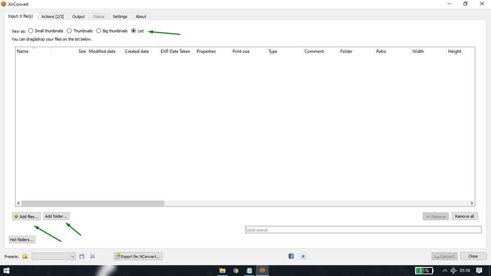
The interface of the software is quite simple. In the input menu, you can add multiple images to compress at a time and you have option
to compress whole folder of photos. You can also set view as
In the output menu, you can set the file path where you want to export the compressed images.
Under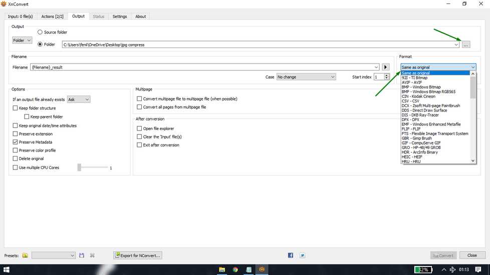
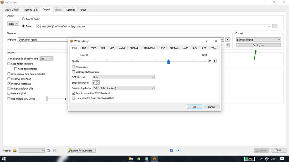
in the seting tab, select the file type you want to export and set the quality of the compressed image. Higher the quality, larger the file
size and compression will be small. And vice-a-versa
add all the files/folder you want to compress in the input menu, and hit convert.
here is the size of folder before and after compression.
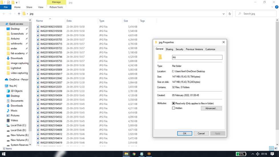
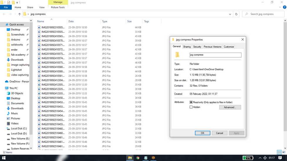
you can twaek the quality and keep compressing until you get your desired image size and quality
<<<---VIDEO COMPRESSION--->>>
for compressing videos, i am using handbrake. Link for handbrake: https://handbrake.fr/
The interface of the the handbrake is quite simple and easy to understand. You can upload single video file or folder containing video
files.
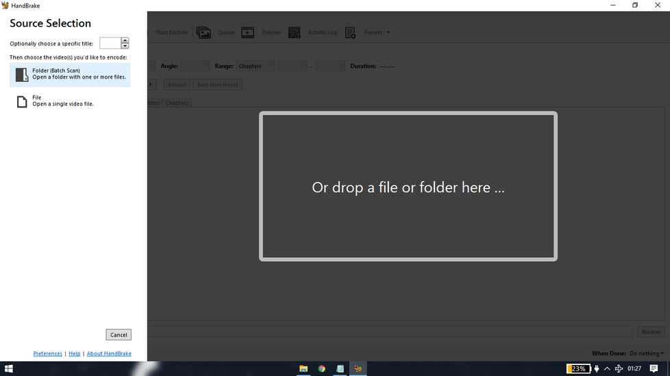
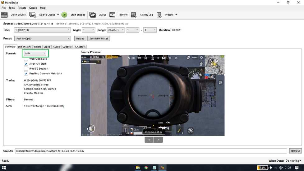
For testing i am currently using a single video game clip. After uploading the video you can set the format of the output file under summary
menu.
under the video menu you can set the quality of the compressed video. Lower the quality of the compressed video lower will be size of video
file and vice-a-versa.
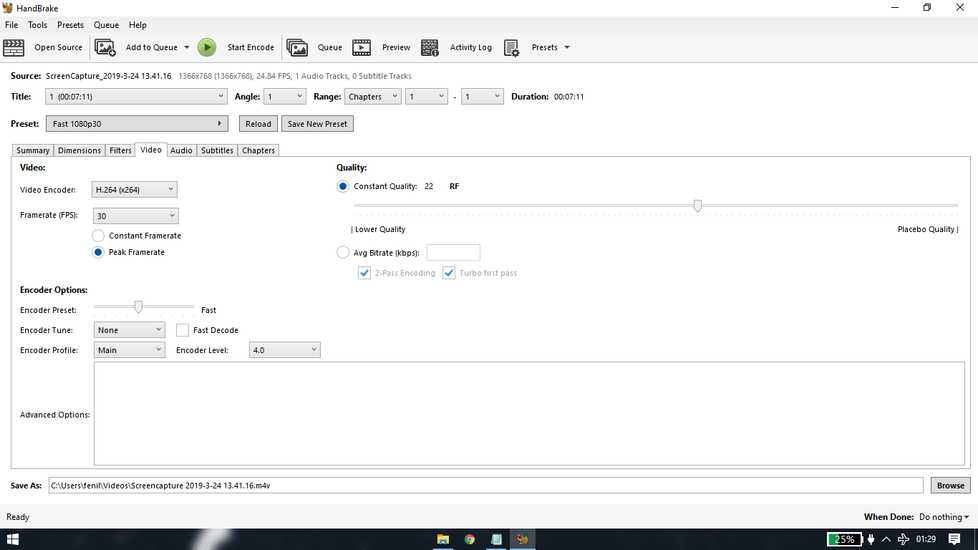
you can set the outpur path of the compressed file at the bottom "save as" file and if you want a particular output path for compressing the
videos in future too, you can set that in the "default path" inside Tools>preference
Here is the size of video file before and after compression
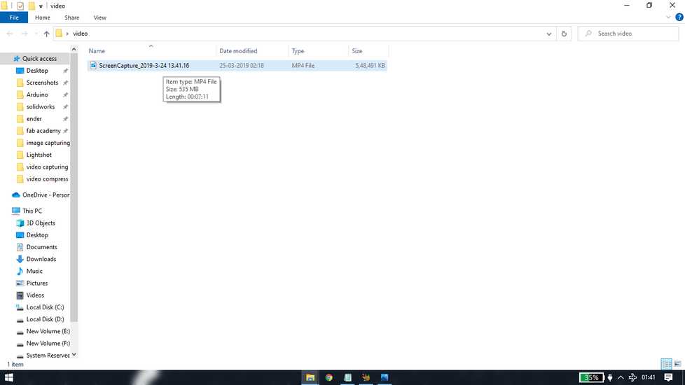
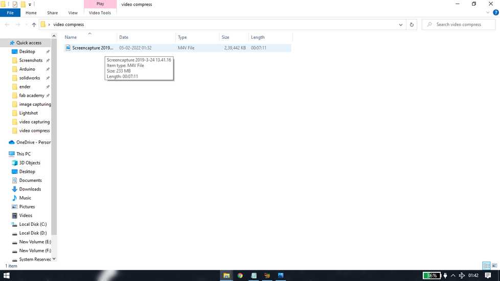
you can twaek the quality and keep compressing until you get your desired video size and quality.
Image capturing and editing
For windows 8 users and above, if you want to take a plain screenshot of your whole screen, you can press
"windows" key + "print screen" key and your system will take a screenshot of your screen. These sceenshot are usually saved in your
"documents" folder.
in order to document, you'll need to capture a lot of photos/screesnhot of the work you're doing. Sometimes you need to make some arrows or
draw a box or add a text in the image to explain what the image is about. To make that simple edits, i am using lightshot software.
Link for downlading lightshot: https://app.prntscr.com/en/index.html
After installing lightshot two things will happen:
1- lightshot will be automatically added to your startup program. You can disable it by going to task manager>startup.
2- the "printscreen" key will be assigned to the software, meaning everytime you press "printscreen" key, the lightshot interface will appear.
In order to disable lightshot, end the task from task manager>background process. In order to again assign "printscreen" button, just open
the lightshot software.
<<<---LIGHTSHOT INTERFACE--->>>
when you press "printscreen" key, a simple interface will open, suggesting you to select area.You can select the are of the screen you want
to capture,
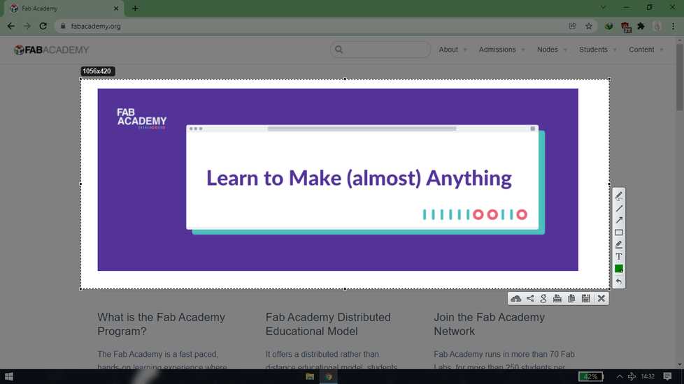
if you want to capture whole screen, select any amount of area and then double-click inside the selected area.

the tools in lightshot in quiet self-explainatory.There is pen, line,arrow, rectangle,highlighter and text. You can try them and play
around
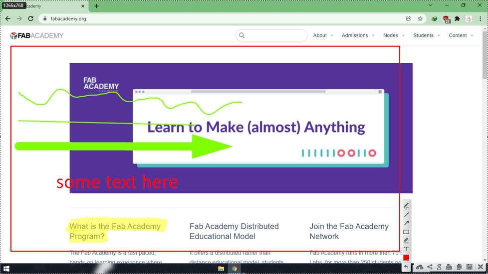
scroll down to increase the size and scroll up to decrease the size
After selecting any tool or right after using any tool, you can use scrool wheel to set the size of the line/arrow.
after the selecting the area or editing, press ctrl+s to save the screenshot. It will generally foung in Documents>lightshot
Video capturing and editing
<<<---VIDEO CAPTURING--->>>
In order to document your work, sometimes you need to show videos
I am using OBS(open broadcaster software) which is open-source software. Link for OBS: https://obsproject.com/
when you'll open the OBS for the first time it'll look something like this,
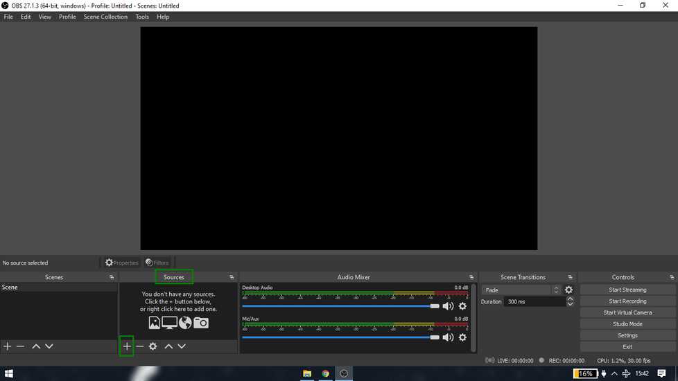
under the source tab, click on "+" sign and click on display capture.
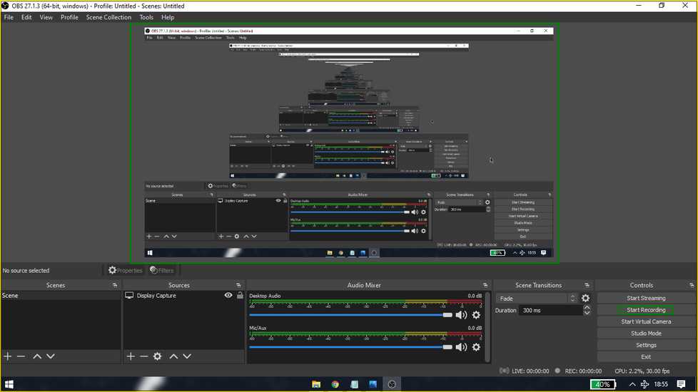
you can see the preview of what the OBS will capture on the first half of the screen. Click on start recording to start recording
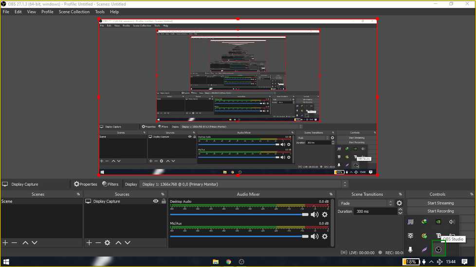
click on the OBS icon inside the hidden icons and the OBS will hide from the taskbar
<<<---VIDEO EDITING--->>>
For editing the videos I am using olive, it has very limited features however it will do the job of editing videos for documentation.
You can download olive from here: https://olivevideoeditor.org/download.php
I downloaded the unsupported version.
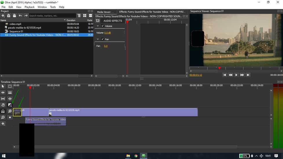
this is what the interface of olive looks like
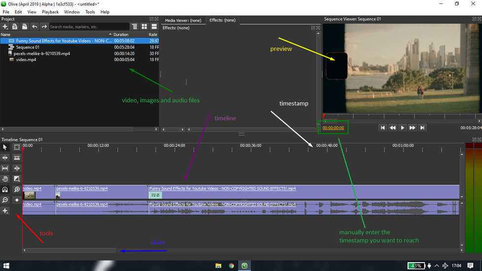
you can add files to edit in the project panel from files>import files
these are the things i am going to do,
1 merge two videos and add a Audio file separated by unlinking and cutting the third video
3 add a transition
4 add a subtitle
[1] merge two video
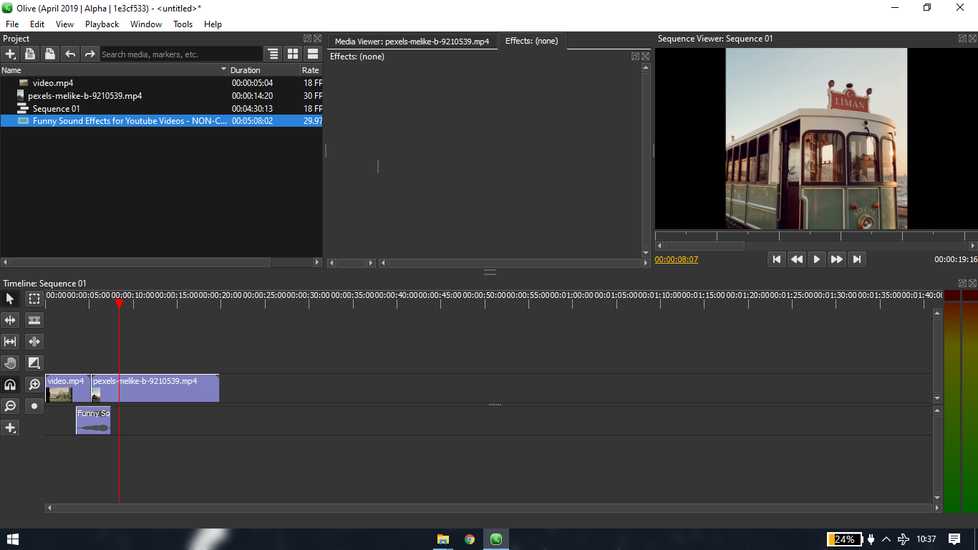
just drag and drop the files you want to edit in the timeline
using the snap tool, make sure there is no space between two videos
unlink the audio file from the first two video
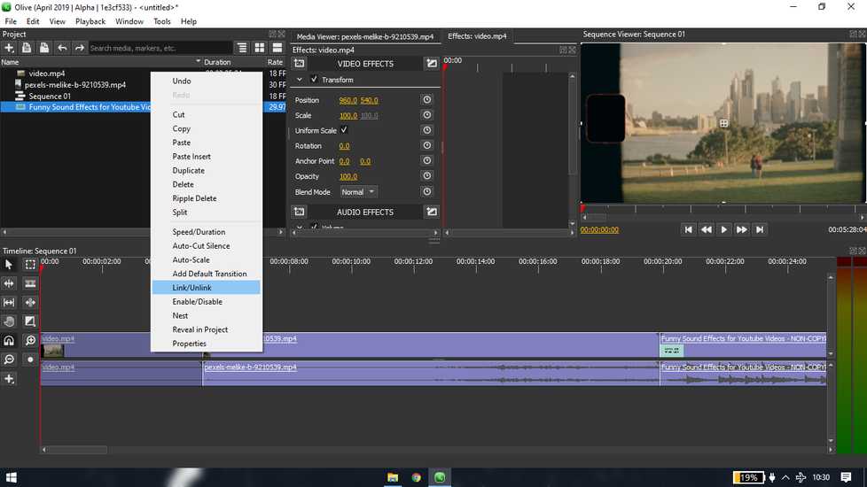
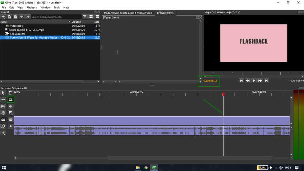
remember the timestamp of the portion you want the audio from. Place the red arrow on the timeline and with the help of razer tool,
split the video. Make sure the razor icon is inside the video timeline.
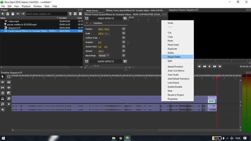
delete the extra video. You can use ripple delete option so that when you split the video, there will be no space in between because two
video will automatically span together.
place the audio in different line wherever you want to place
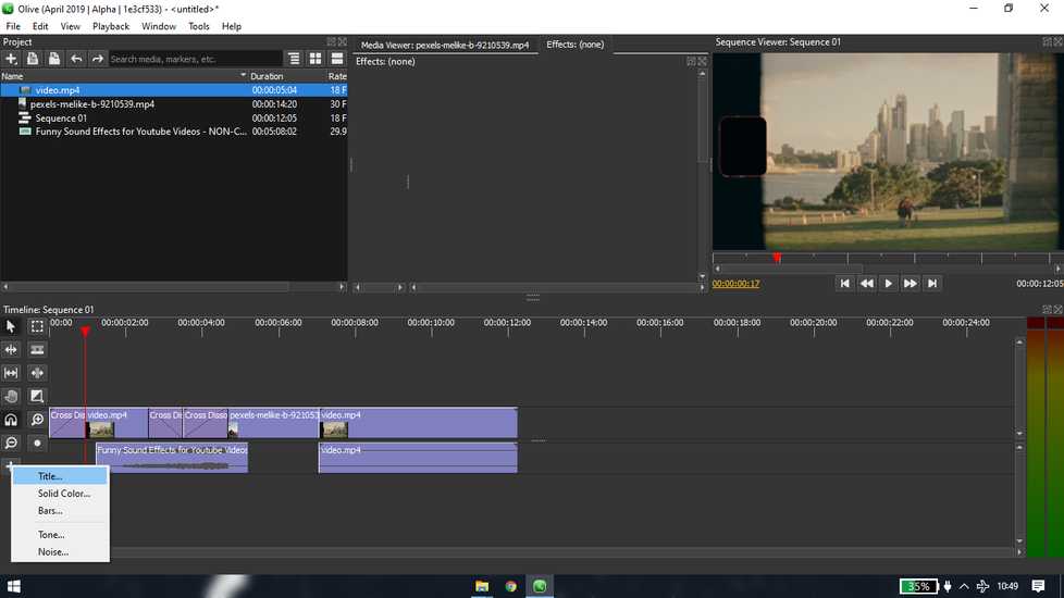
[2] add transition
in the transition tab inside tools, select cross disolve. You can use the transition at the end or start of the clip. So click on corss
disolve and drag the area which you want to cover in the transition
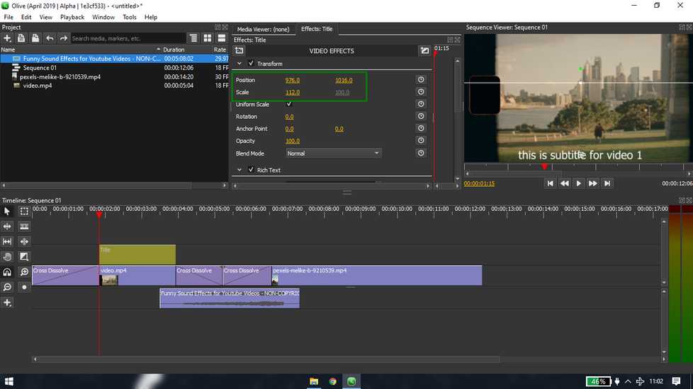
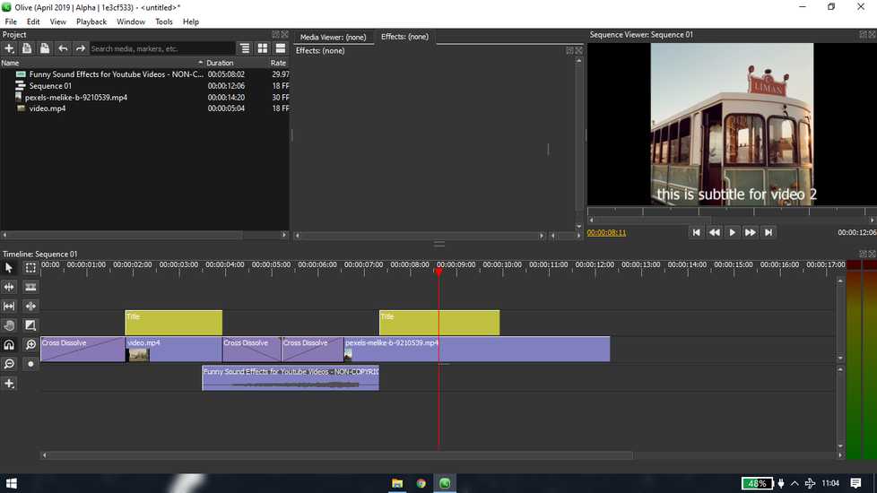
[3] add subtitle
place the red pin where you can to add subtitle. From the tool box, click on "+">title
drag the box to the area which you want to cover in subtitle. Note that do not add the text filter onto the video timeline but onto different
timeline. Double click on that yellow text box to edit text and position the subtitle box.
reference link: https://www.youtube.com/watch?v=UJFkPjHxccc
Fusion 360
i have a bit of experience in Solidworks, however this is the first time i am using fusion 360. The interface and method
of sketching/designing is quite different from solidworks, it did't took a long time to adapt to a new software
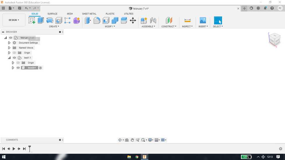
The first step is to save the file
create component
if the created component test2 is created under component test1, then drag the test2 component and place onto saved file name.
the circle beside the component is to activate/deactivate component.
<<<---EXTRUDE BOSS--->>>
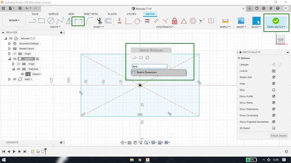
select any component and create new sketch under "create" tab
draw any sketch and set the dimension., If you don not want to set the dimension right after sketch is drawn, hit escape key and set the
dimension later using sketch dimension
feature under "sketch" tab. if you do not want to search for feature, just hit "s" key and a search window will pop, search the feature from
there
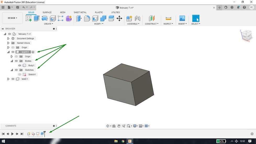
hit finish sketch once you are done making the sketch. Then under solid tab,use the command "extrude" and set the distance. you can even
drag the component manually. Again you can use "s" key to search the extrude command.
after extruding you'll see that under the component there are two sub-folder, sketches inside which there will be all the sketch under that
componment and bodies where there will be all the bodies under that component. You can edit feature/body from there and you can also edit
from the bottom tab. Right click and you will have option on edit feature/sketch.
Under document settings, you can set the unit of measurement.
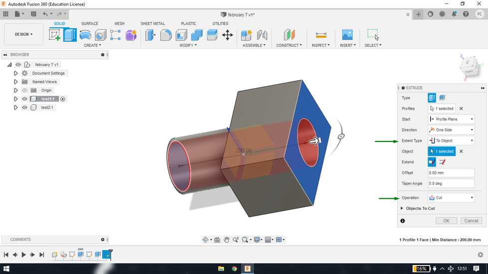
<<<---EXTRUDE CUT--->>>
to draw a sketch you'll need either plane or a surface. In m y case i am drawing on a surface, click on surface and "create sketch"
instead of drawing another circle i am just using offset feature. You can use the button to manually set the offset
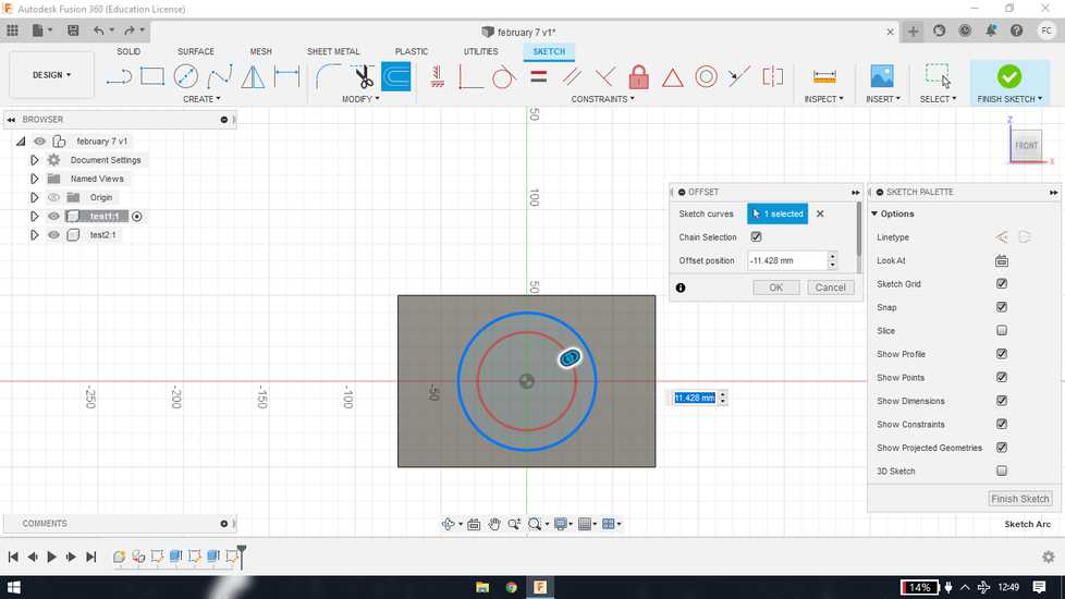
use same extrude feature but instead of pulling it in the same direction, pust in the opposite direction to make a cut. You can also set the
"operation" to cut. Instead of calculating the distance or setting absurd amount of distance to cut, set the extent type to "to object" and
click on the surface where you want to end the extrude cut.
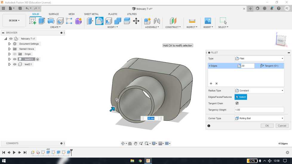
<<<---FILLET--->>>
after selecting "fillet" feature, select the edges where you want smooth edges and set the radius
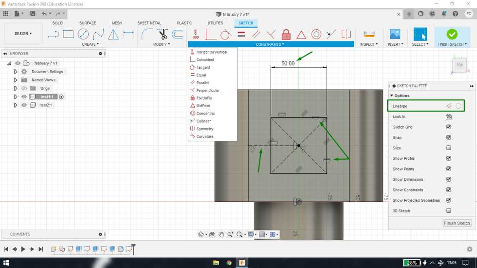
<<<---DRAFT AND RELATION/CONSTRAINTS--->>>
it is great practice to make your sketches fuly defined. Fully defined means your sketch is fully constrained and nothing can be change
accidentally. You can'y have your sketch moving freely all over the canvas with no dimensions set. So here i am constraining the sketch ihave
drawn.
First set the dimension, i selected the two perpendicual line of square and set equal relation using constraint.
Second, limit
the vertical movement by drawing a construction line connecting midpoint of square and midpoint of left line and set horizantal relation from
constraint.
Third, limit the horizantal movement, for that i selected midpoint of bottom line and midpoint of square and gave them
vertical relation using constraint.
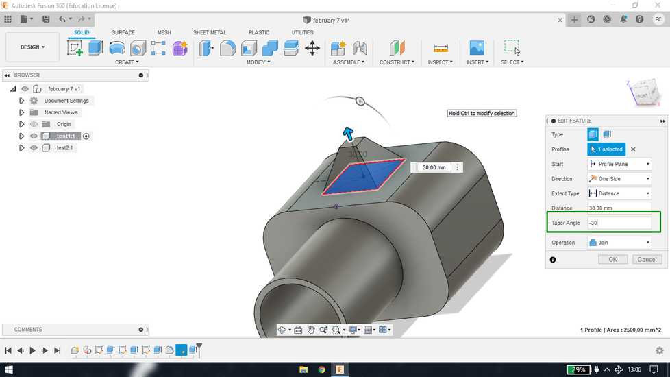
draft basically means the end of the extude is either shrinked(-) or expanded(+). While extruding(join) set the value in the "taper angle"
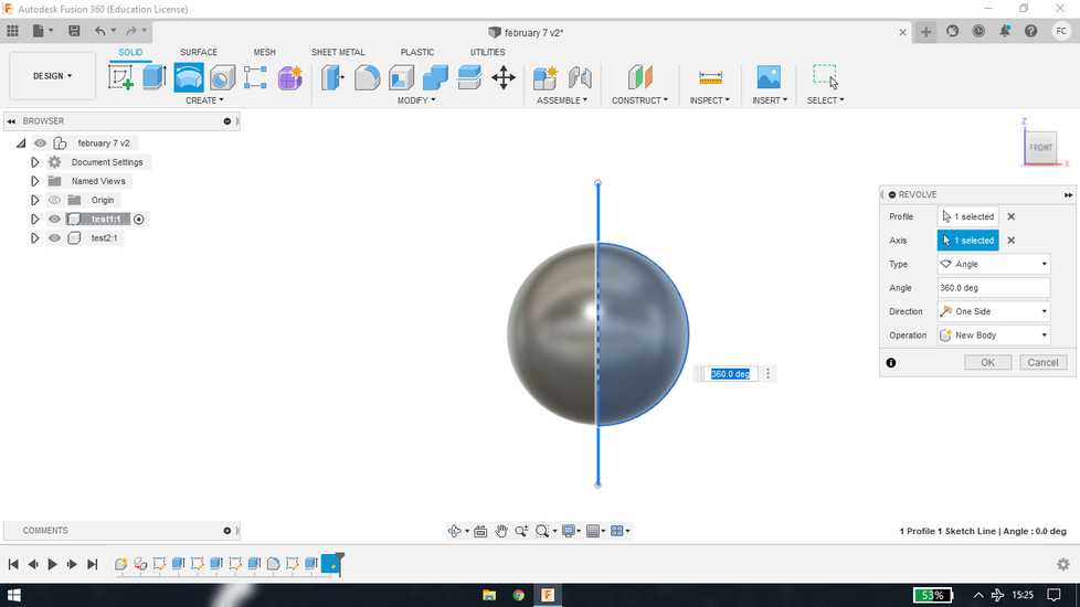
<<<---REVOLVE--->>>
draw a line around which yu want to revolve the shape. And then draw the shape you want to revolve.
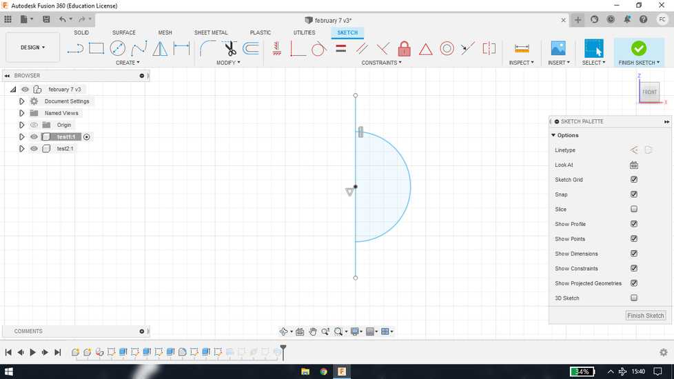
in revolve feature, select the shape for profile and select line for axis
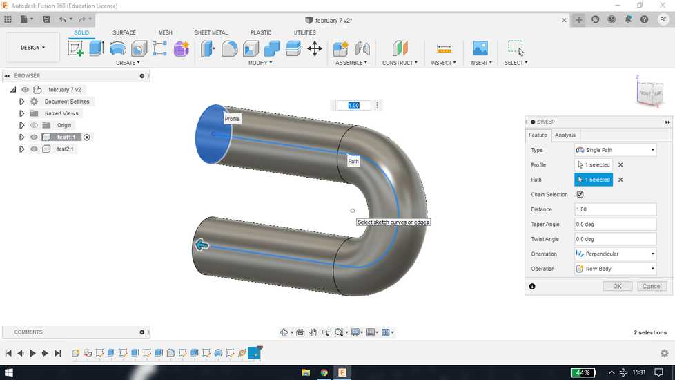
<<<---SWEEP--->>>
create path
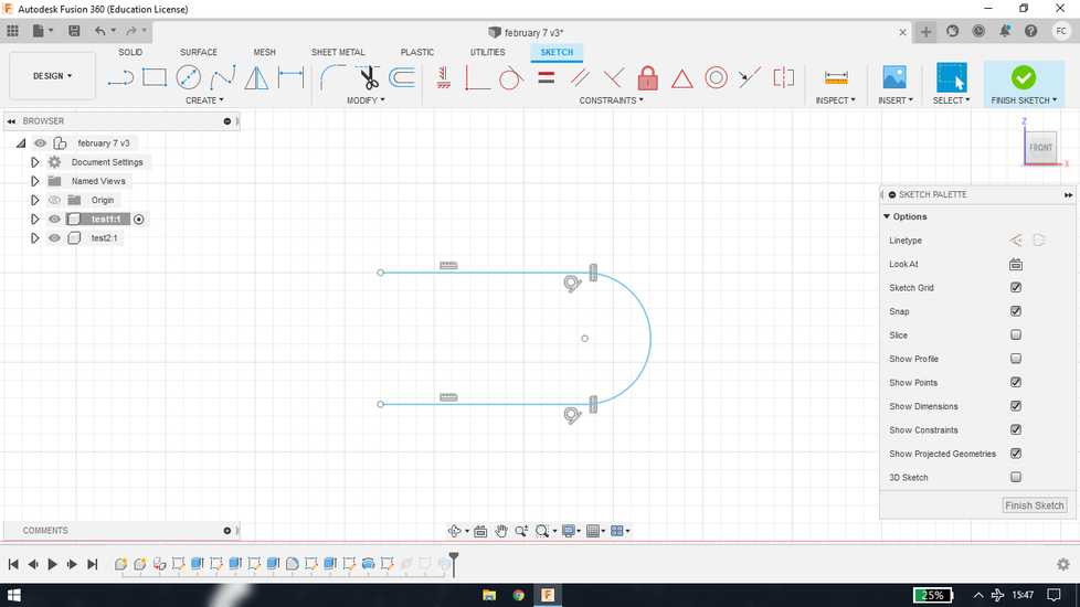
go to construct>plane along the path. Select the path to create plane
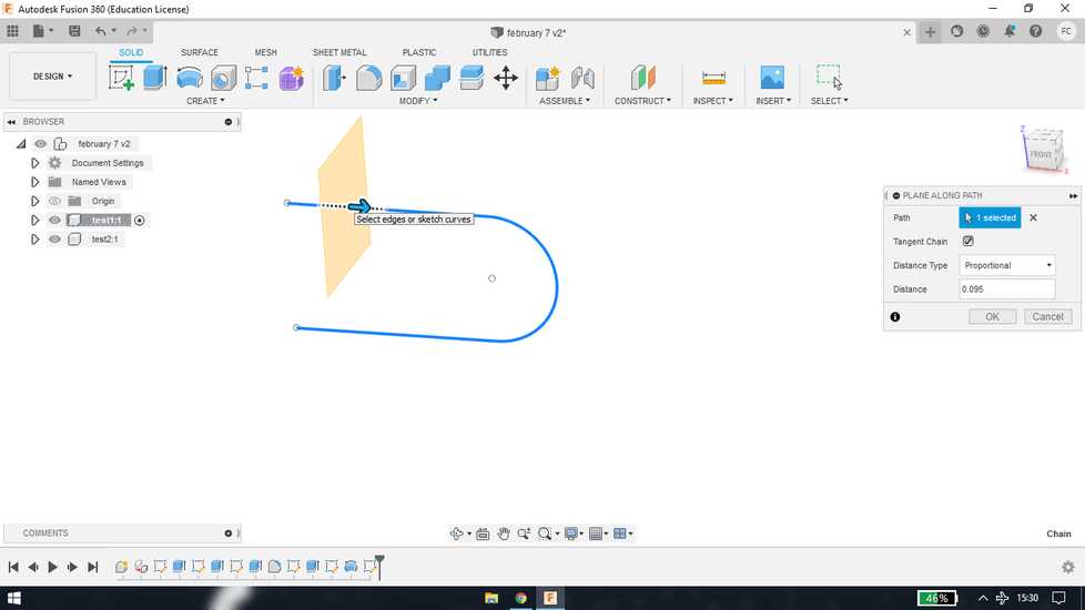
create sketch with the help of created plane and inside that create profile
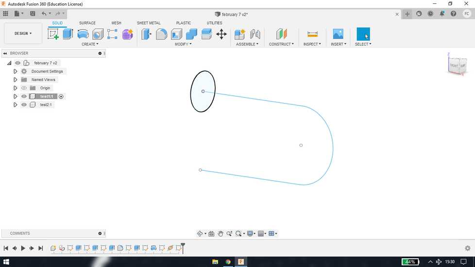
in sweep feature, select line for path and select circle for profile
FreeCAD
i wanted to explore the freecad to see how is this open-source software is compared to the commercial ones
the steps before starting to sketch is similar to that in fusion 360:
save the file first
under the part design mode: Create body>create sketch>select plane.
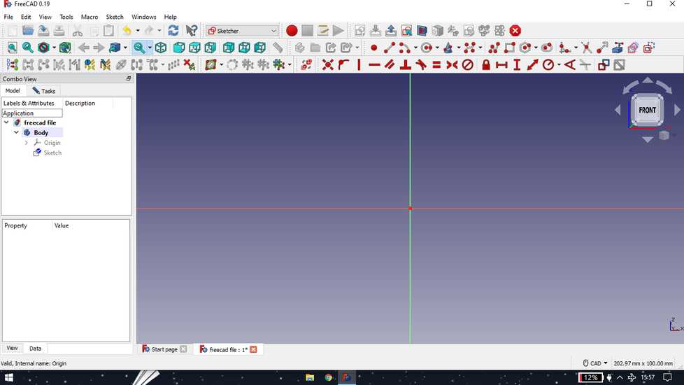
exit the sketch by hitting escape or one of the button on the top. Click on pad under sketch tool or on the icon
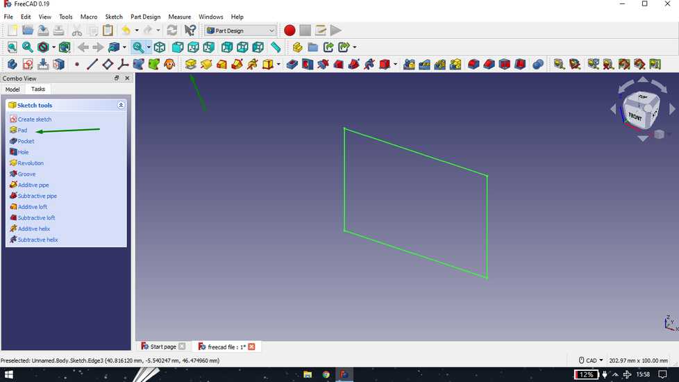
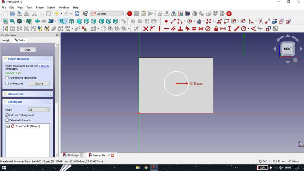
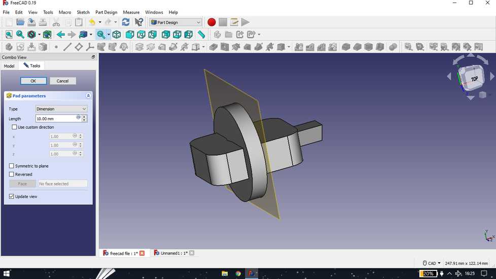
<<<---PAD AND POCKET--->>>
click on any surface and under task, click on create sketch. Draw any shape. I i tried to give constraints pther than dimension, but coul't
find any midpoint and also was't able to select the edge, like you do in solidworks and fusion
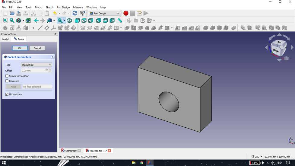
exit sketch and select pocket
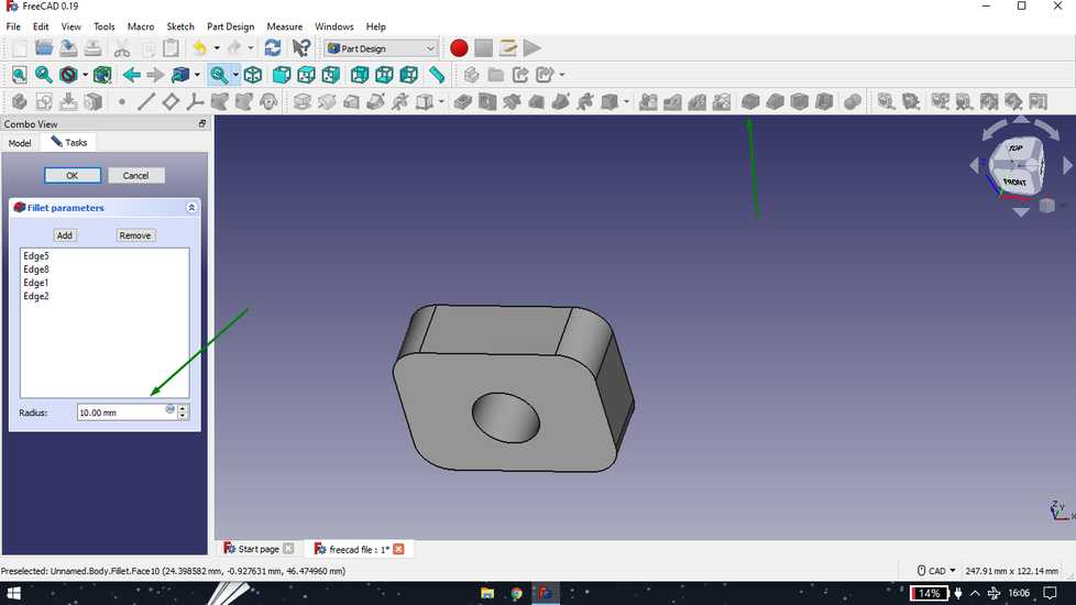
add fillet
<<<---MIRROR FEATURE--->>>
draw object on the side
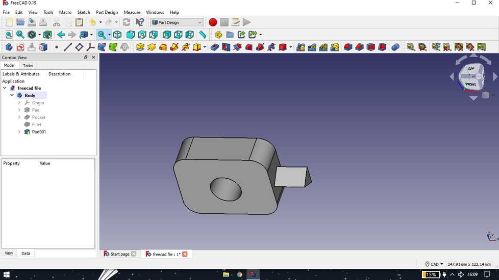
i observed that there is no plane in the middle so i created the plane
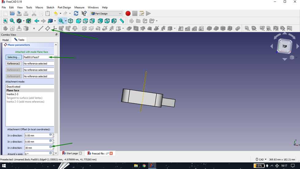
i was't able to give reference by selecting two surface, so i manually added the dimesion to set the plane
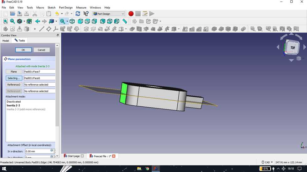
i then used the mirror feature after selecting the plane and surface to mirror, but wasn't successful
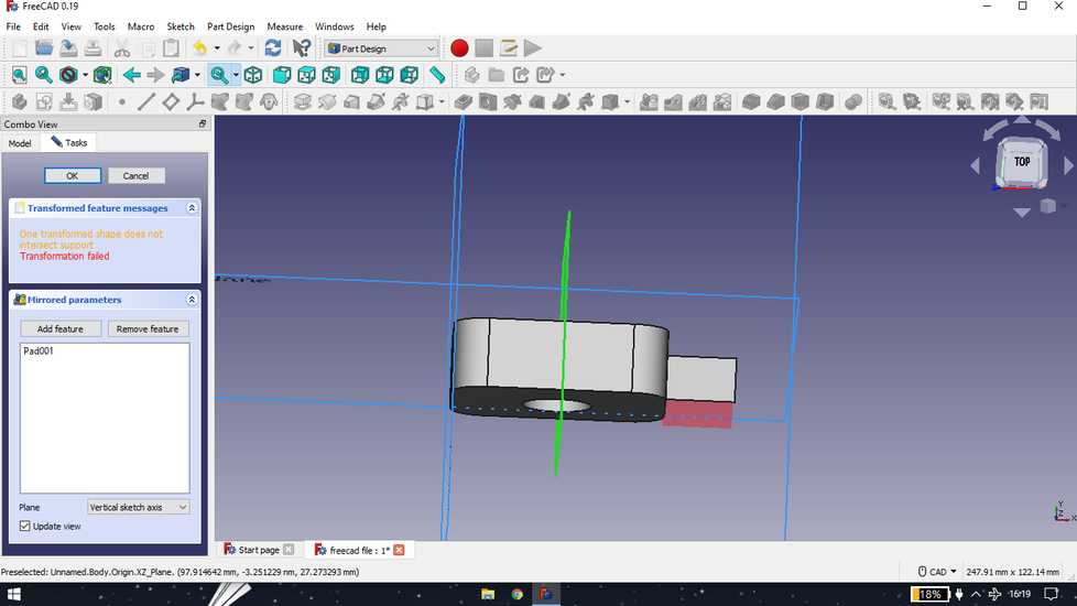
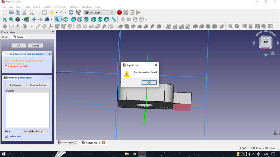
the plane that i created works well though
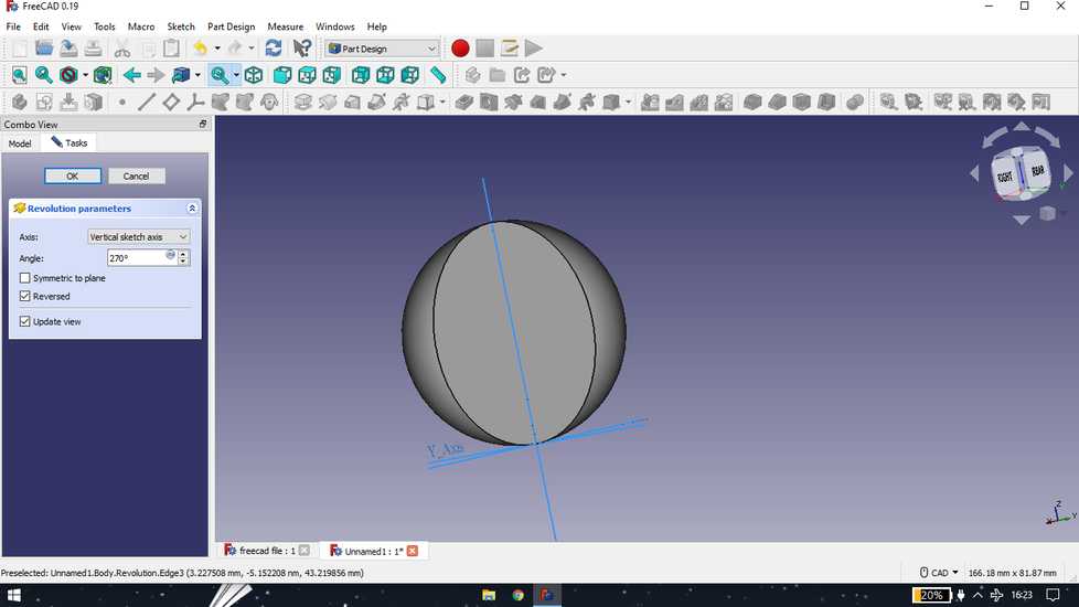
<<<---REVOLVE FEATURE--->>>
draw a sketch,exit the sketch and select revolution

set degrees you want to revolve
Solidworks | making final project cases
Before beginning of the fab academy course, i had a better hand at solidworks however i decided to explore something new so i practiced and went
with fusion 360 to design every model during the fab academy. But, during the final project, circumstances were such that i eventually went back
to my comfort zone and designed the cases for the components and project board in solidworks.
<<<---ULTRASONIC CASE--->>>
I designed the case for ultrasonic sensor as a single part,
and then with the help of reference geometry, i created a plane in the middle of the model and made a rectangle,
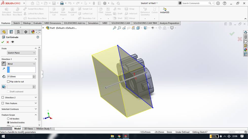
with the help of "Extruded cut" i cut one side of the model and exported the design as STL file,
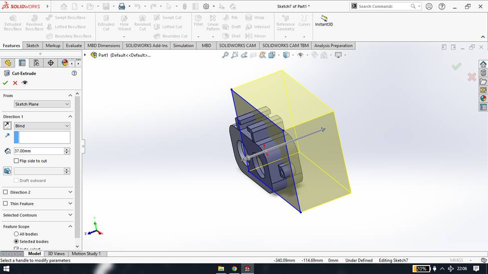
i then deleted the cut extrude feature and again use the extruded cut feature using the same old sketch and cut the other side of the model and then i exported the design as STL file,
after the case was ready,i designed a holder for it,

you can download the Design file for the ultrasonic case from here, ultrasonic case
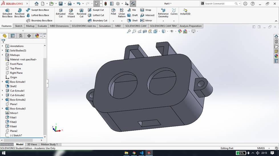
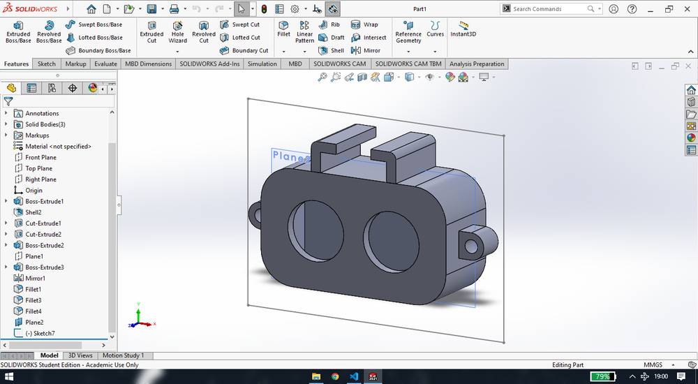
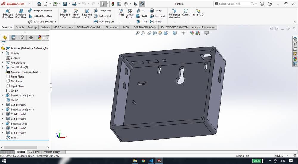
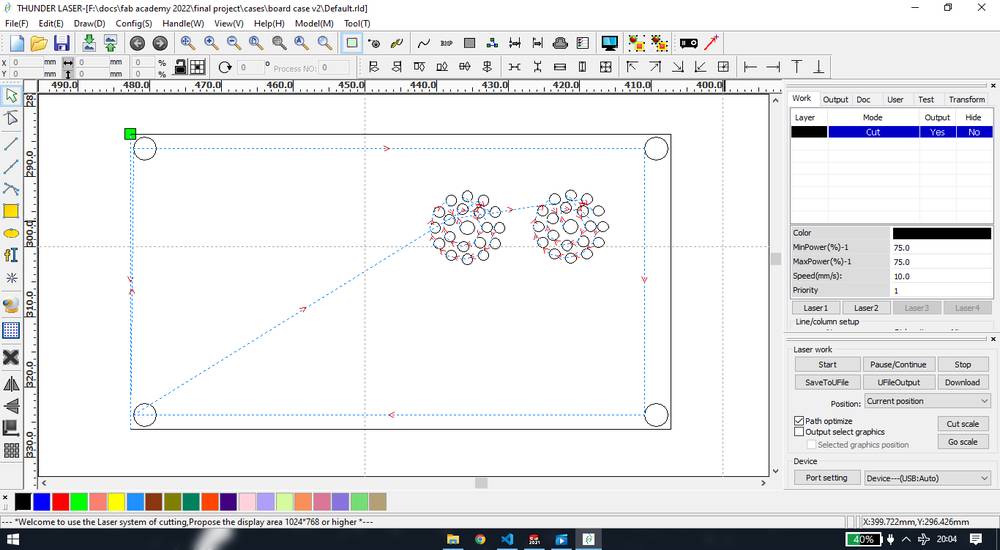
<<<---PROJECT BOARD CASE--->>>
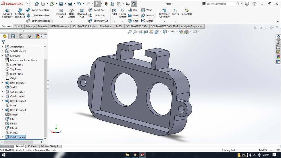
I designed the case for my project board in two parts,
While designing the bottom part of the case, i gave the provision for push buttons, female jack for external power supply, slots for the wire connector to go through, slots for bolts onto which i was going to fix the final project board since the board didn't had any holes in it, slot for the FTDI converter to go through and lastly a slot for the nail onto which i was going to hang the case.
Here is how the bottom part of the case looked like,
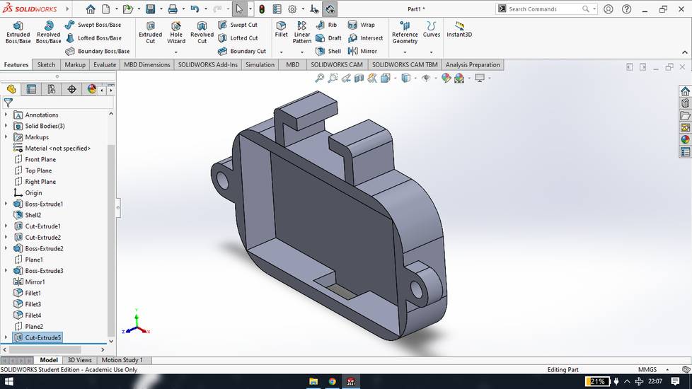
While designing the top part of the case, i gave a slot for the wire connector that connects the OLED and i gave 2 slots for the signal and ground pins of the two LED0-buzzer. However i did not find the 2mm screw to fit the OLED and so i used double sided tape to fix the OLED and PCB with LED-buzzer. I also designed a border so that i can cover the OLED and PCB with some acrylic sheet to save them from dust.
This is how my top part of the case looked like,
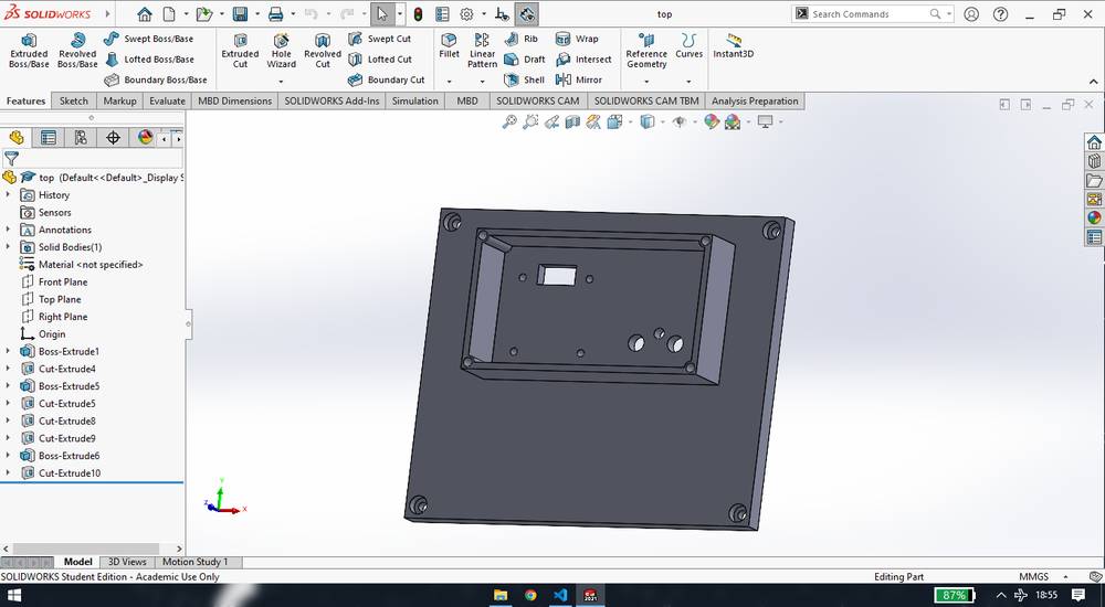
And this is how my top part of the case looked like after adding the logo of my project and adding the fillet features,

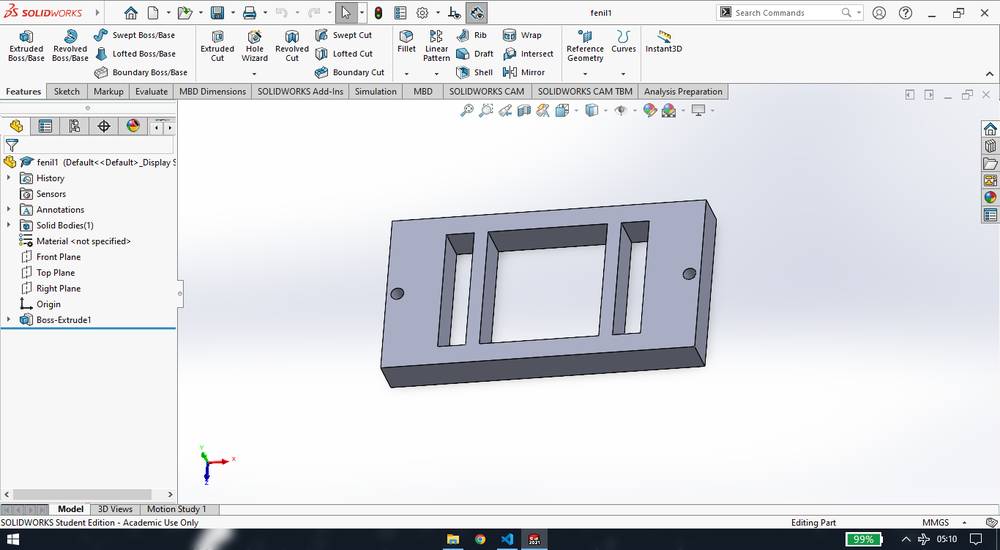
<<<---WATER SENSOR CASE--->>>
I designed the case for water sensor in two parts,
I made the casing for the water sensor/screw connector with needle keeping in mind the dimensions with 1.2mm diameter needle inserted. This is how the top part of the case looks like,

here is how the bottom part of the case looks like,
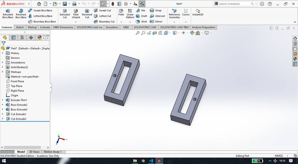
Design file for the water sensor/screw connector w/needle case,
water sensor case
Later when the drop was not easily sliding through, i had to change the needles and the needles i replaced with were short in length. And so i had to change the design of the bottom of the case and also enlarge the slot onthe top of the case. My colleague, Kiran Wakchaure helped me with designing and cutting that part in acrylic in the laser cutting machine, and my other colleague, Ashish Shende, helped me with enlarging the slot on the top of the case,
you can download the dxf file of the bottom part of the screw connector here,
screw connector bottom part
I then designed the cover for the OLED and the PCB and designed small holes over buzzer so the sound can penetrate. FOr the border an4 4 holes i used the "Convert entities" features and then add holes in circular pattern over the buzzer(took tentative measurements of the position of the buzzer) hut unfortunately i lost the original part file.
You can download the rld file here,
acrylic shield
Inkscape
in 2d design there is vector design - made of lines where the object won't distort no mater how much you zoom and there is
raster - made of pixels where the object will distort if you zoom after a certain point
There are no pointers for the description of inkscape,
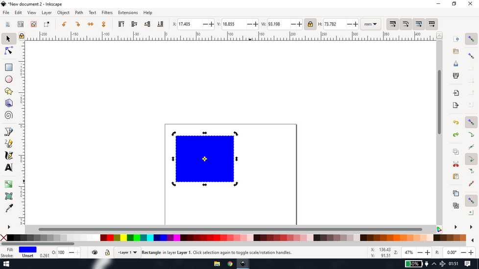
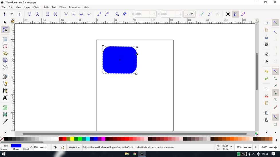
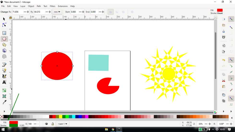
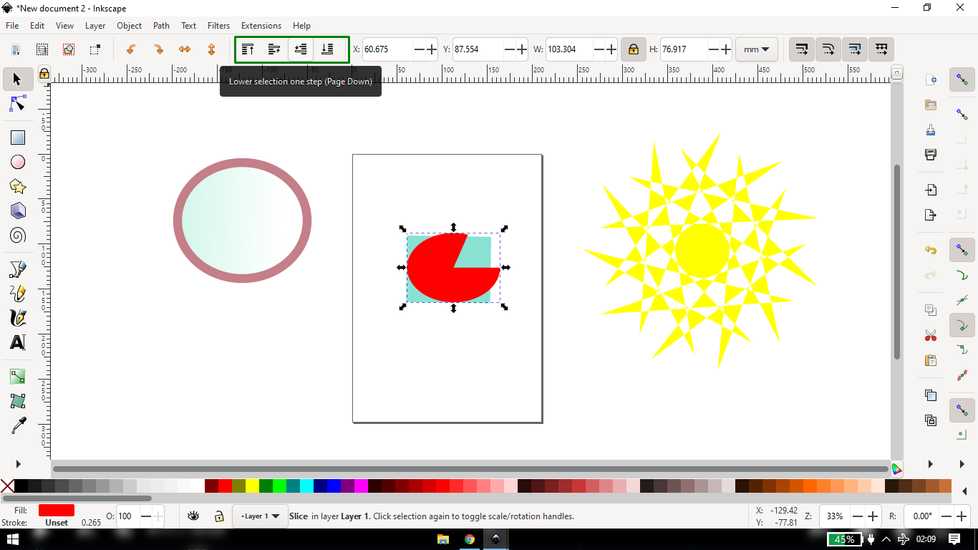
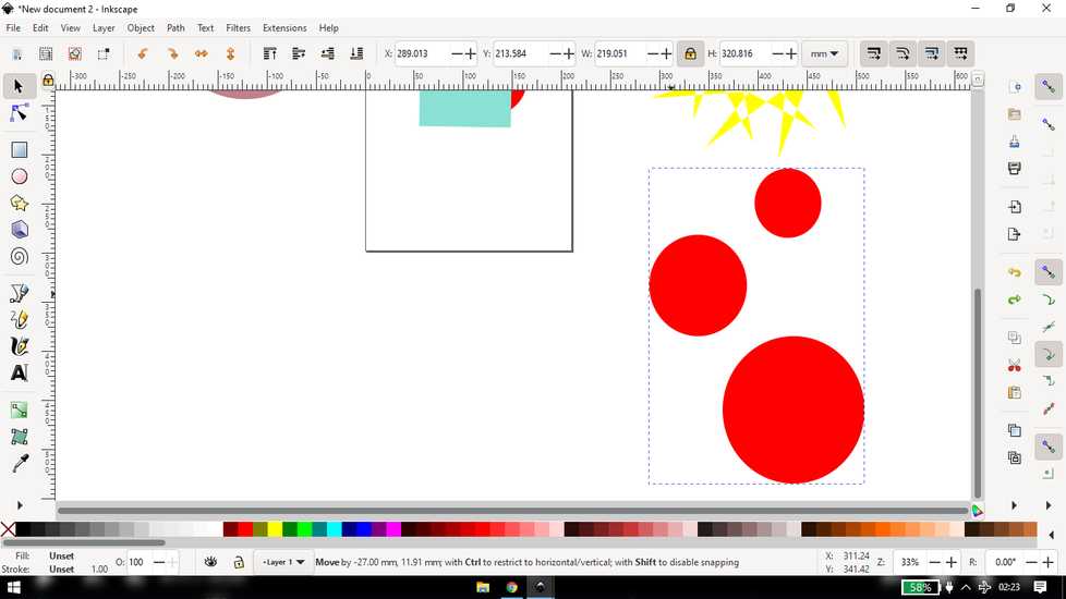
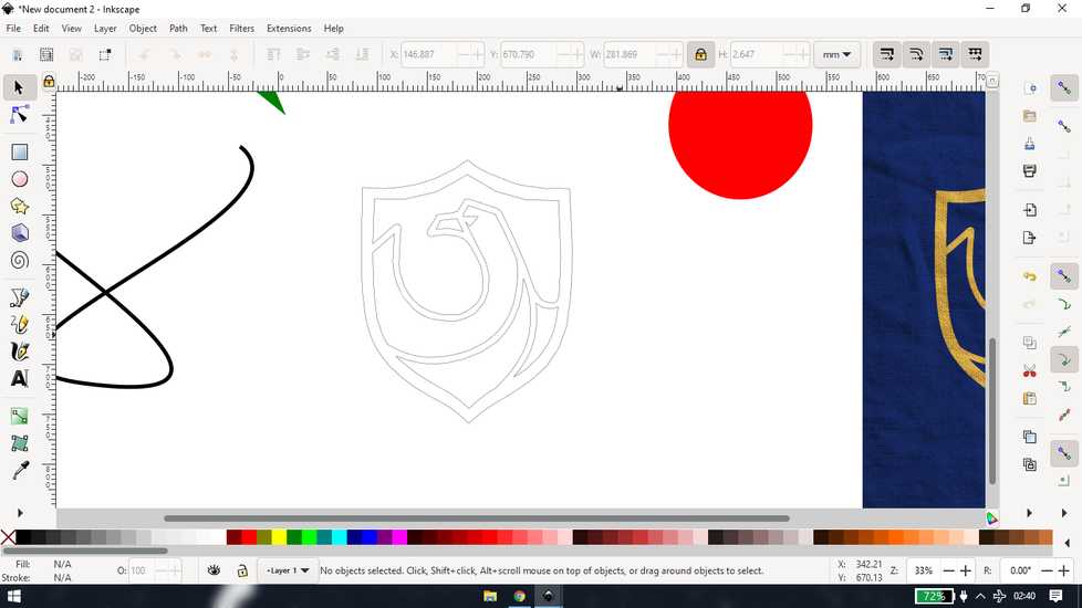
Draw any object from the tool bar on the left, and left click on any color option on the bottom to fill the color
click once and you will get option to re-size

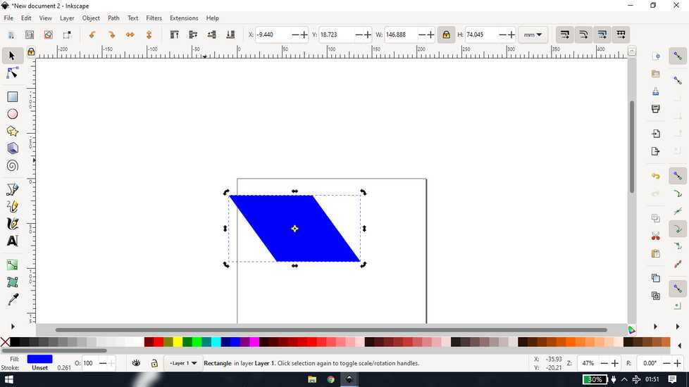
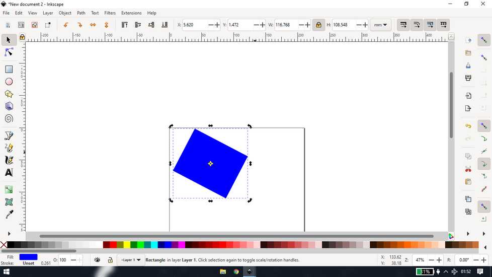
click again and you will get option to change shape of the object
double click andyou'll be able to give rounded corner
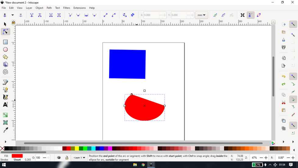
There changing of shape differers, depending on the type of object

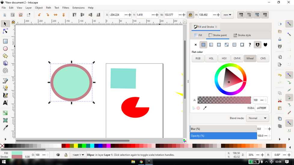
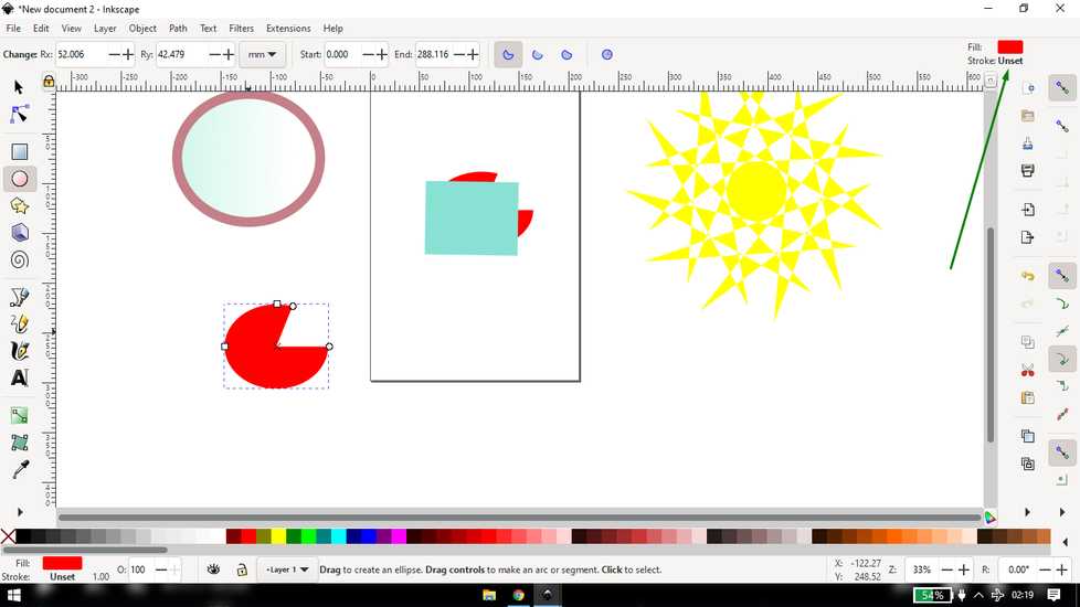
you can change the fill and stroke of any object, fill is the inside color and stroke is the outline of the object
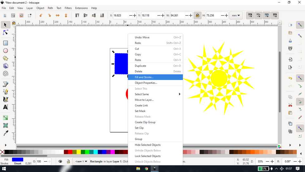
to add a color to the stroke, do "Shift+letft click"
you can tweak the settings as per your desire
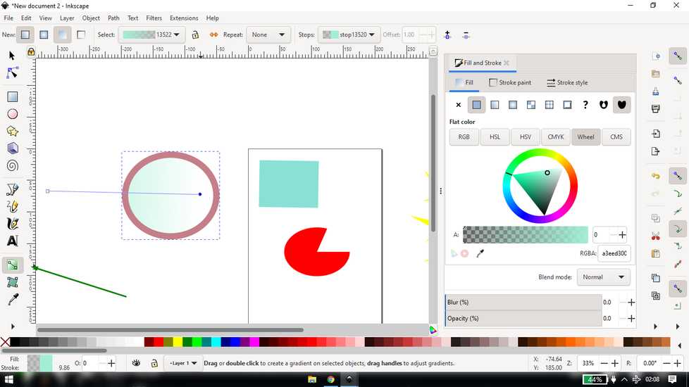
you can also add gradient
you can change the positiion of the object, like lift the object from the bottom and vice-a-versa, using the four tabs on the top
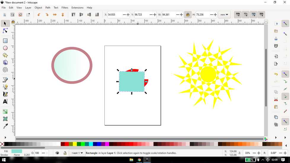
every time you make any change in object, inscape will remenber and will set that as standard for fututre, you can undo the colors from the
"fill and stroke" tab on the top, if you want to undo the shape, you have to do it by clicking twice(not double click)
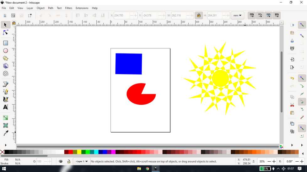
you can group multiple object so that any effect you give to one object, all the other object will be affected.
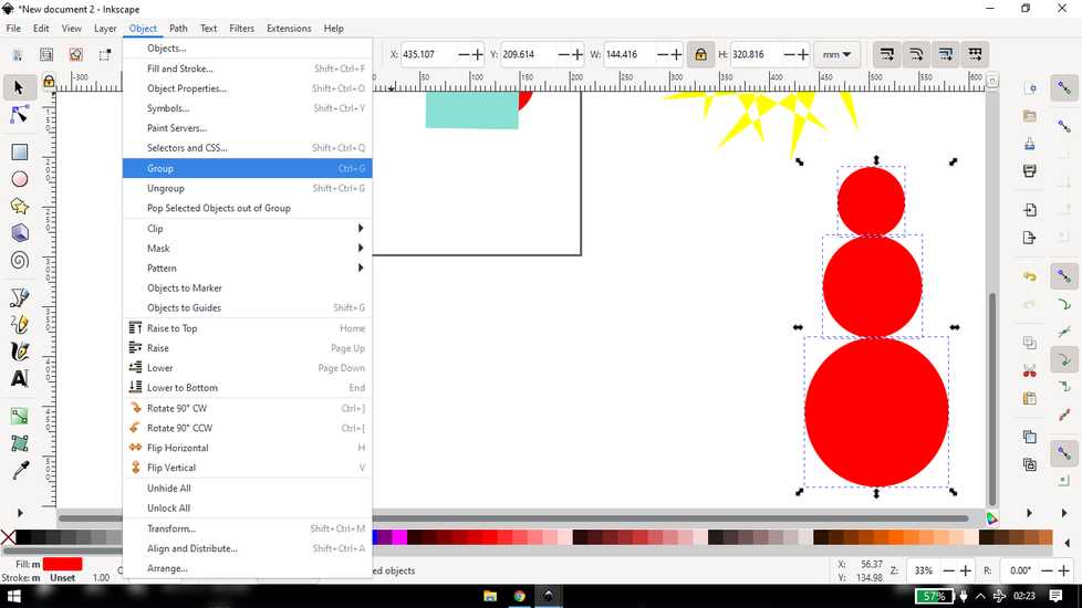
to temporarily make any changes, double click>make changes like change the position/shape/color>double click and now the group is updated
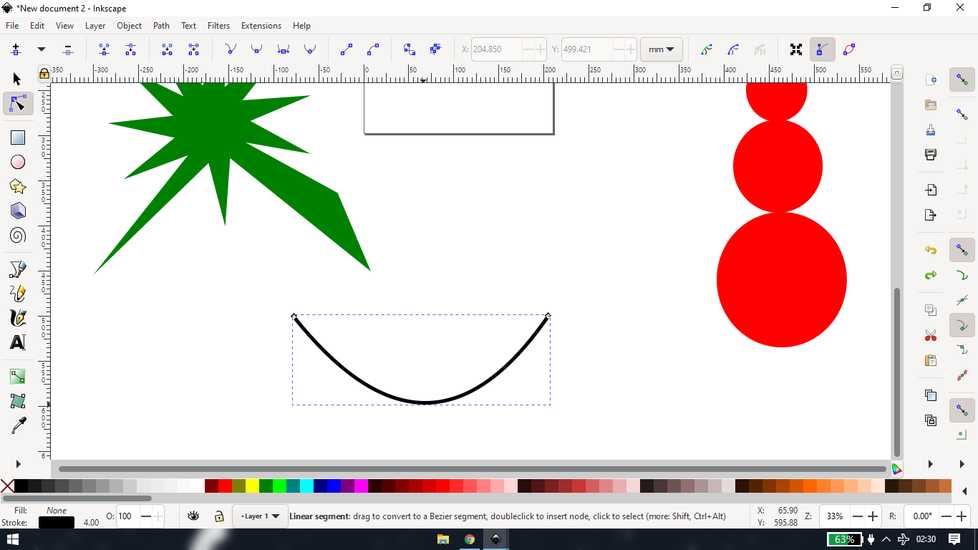
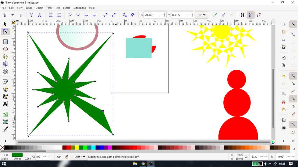
when you draw a path like line,you can change the orientation by just clicking and draging where you want to changet he shape. A line will
appear on the "node" you can play with them to change the shape
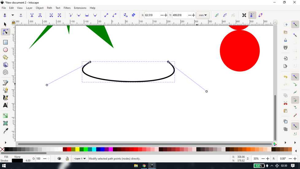
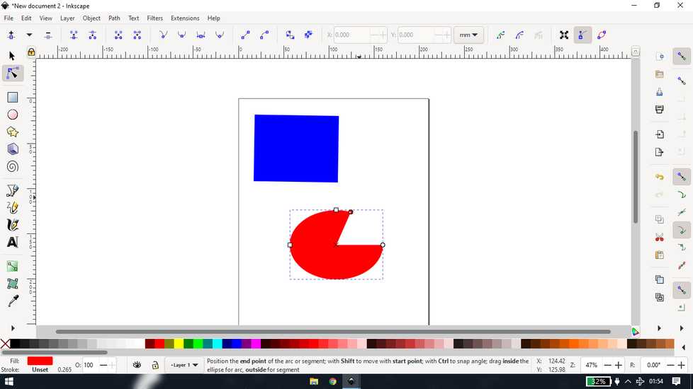
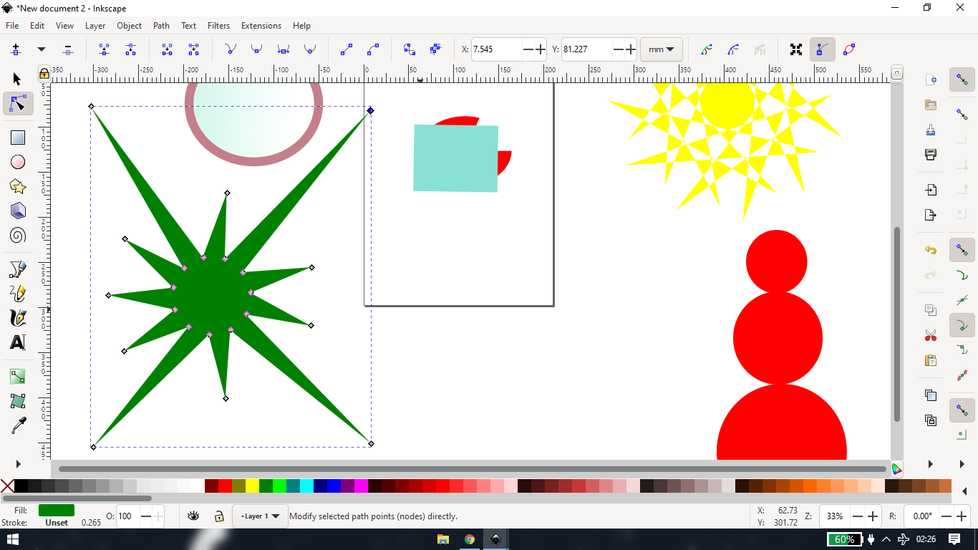
you can also add a node by selecting "edit path by node" and double-clicking on the edge
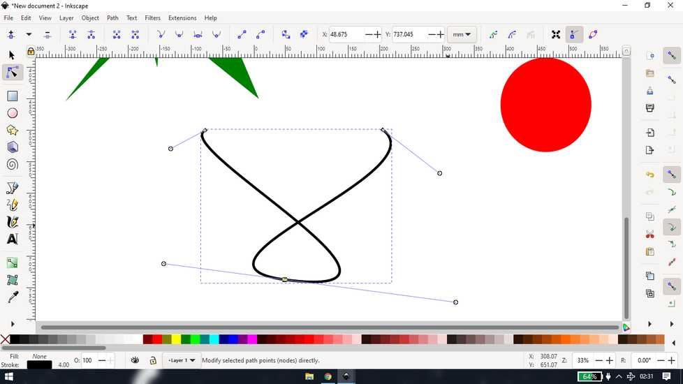
you can't do the same on an object, so you convert any object to path
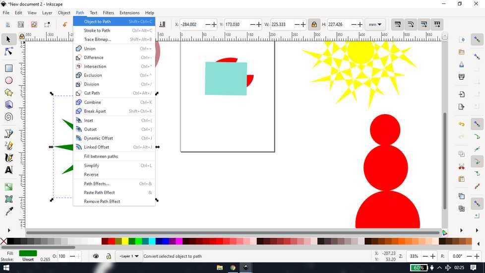
then you can treat any object as a path, tweak the shape by using node and also add a node
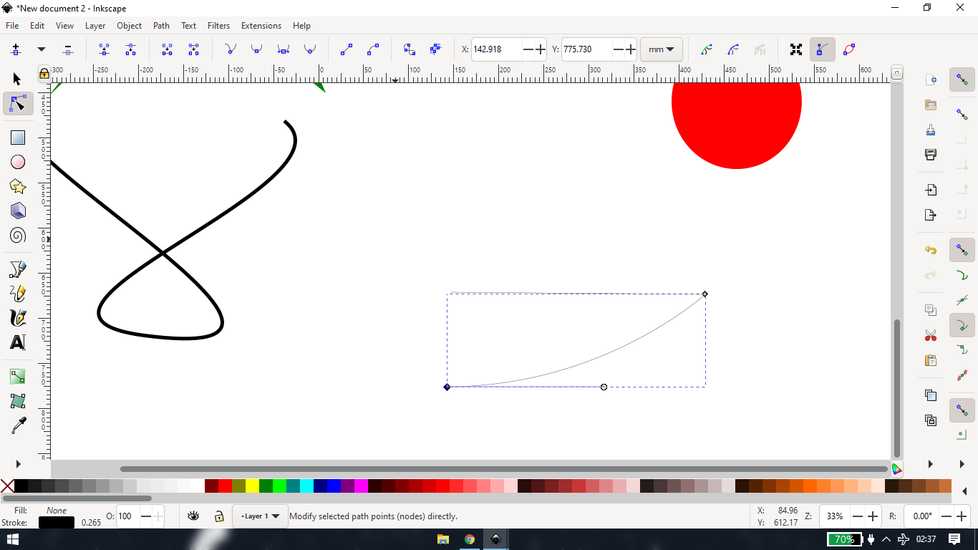
you can draw lines and add curve to them using bezier tool

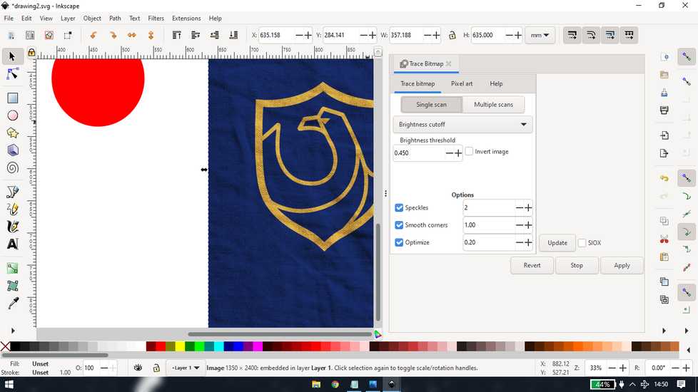
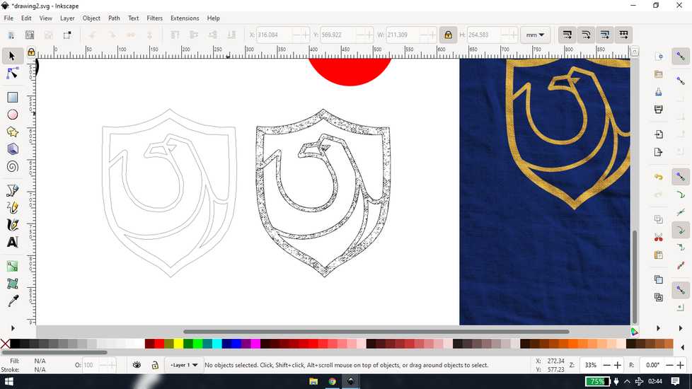
you can apply the same principle for tracing an image. To insert image, go to File>Import
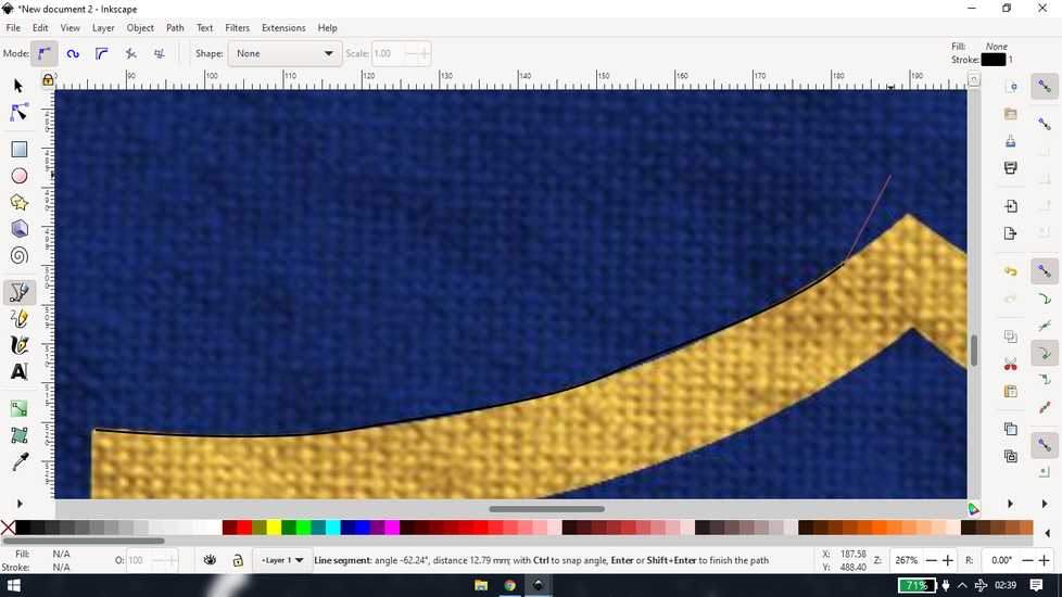
instead of tracing the edges manually, you can use trace bitmap option and inkscape will do that for you, however you have to tweak the
settings in order to get desired results
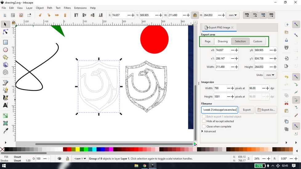
you can save to svg file from "save as" to save the project, so that you can make changes in the future. you can also export the file
in image format
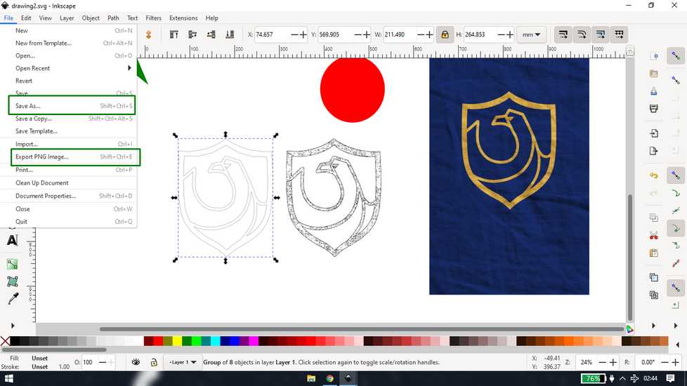
to export, set the output path and select what you want in the image. Page means anything drawn in the box, drawing means everything you
have drawn, selection means the objects selected
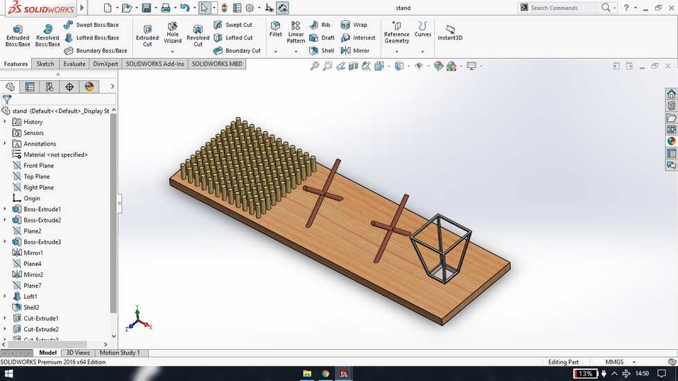
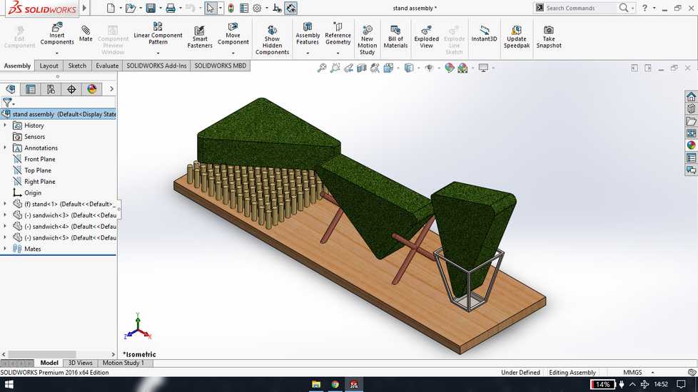
Solidworks | making stand
I was more comfortable in solidworks so I designed a stand for Sandwich, to prevent Sandwich from condensation
Blender
blender has a lot of application however i have only explored one aspect that is simulation or physics properties
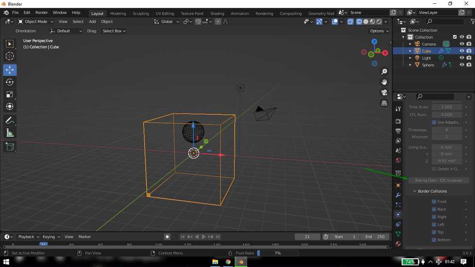
The highlighted tools are the one i am going to use the most
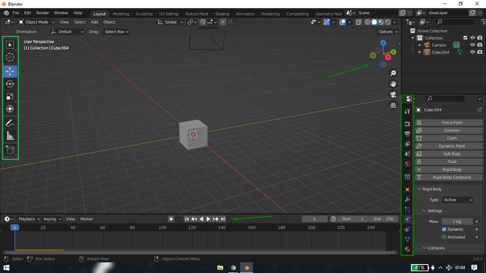
on left there is select, move, rotate, scale tools. On the bottom there is frame and pause/play, forward backward button. On right there is
viewpoint and at the bottom right there are features like physics property, material property etc
<<<---RIGID BODY--->>>
select the object and set the rigid body type as "active"
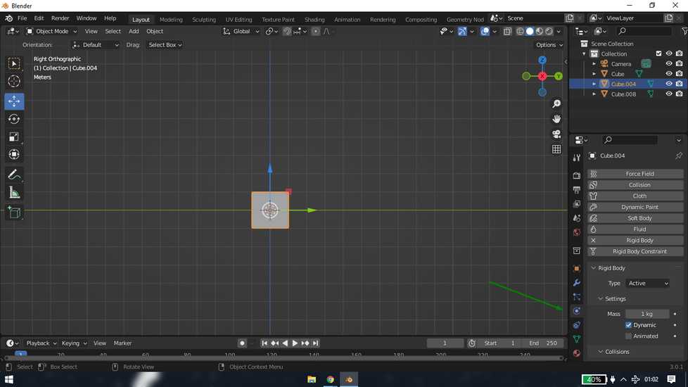
make duplicates by pressing Shift+D and make a wall. You can adjust the position before confirming by hitting enter.
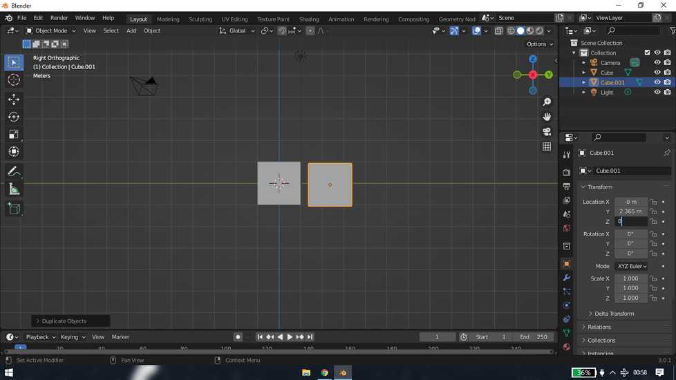
in order to avoid al the block from falling downward, make a plane at the bottom. Set the rigid body type as "passive"
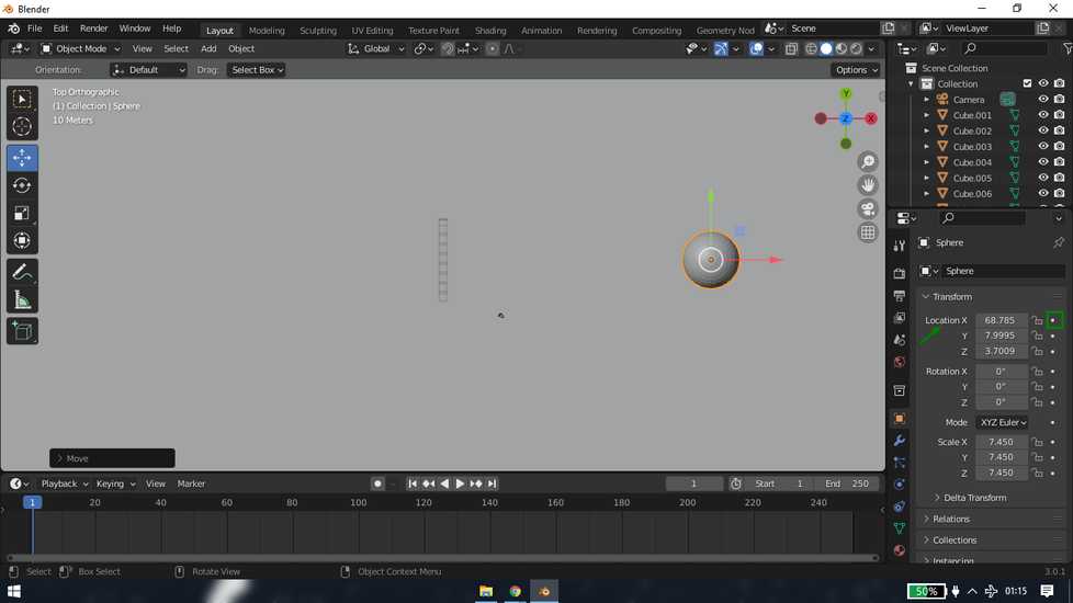
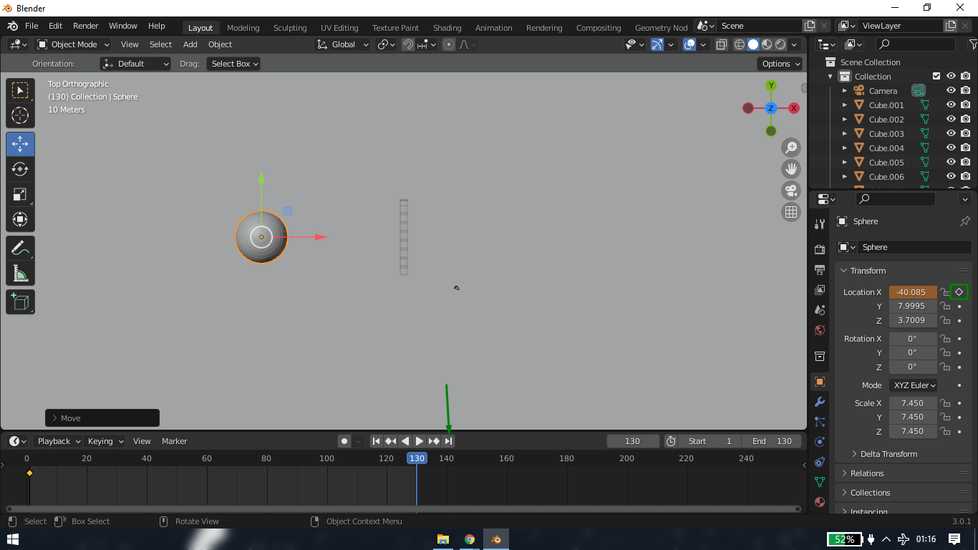
add uv spehere and scale and move however you wish. Place it perpendicular to the wall. Create animation of sphere passing through the wall
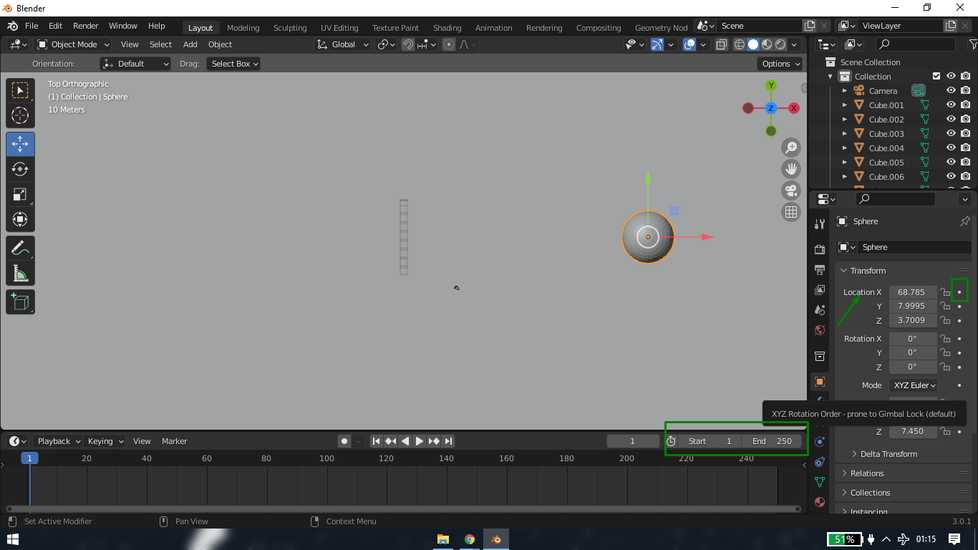
by creating first key at the start position and second key at the end position. You can set the number of frames too.
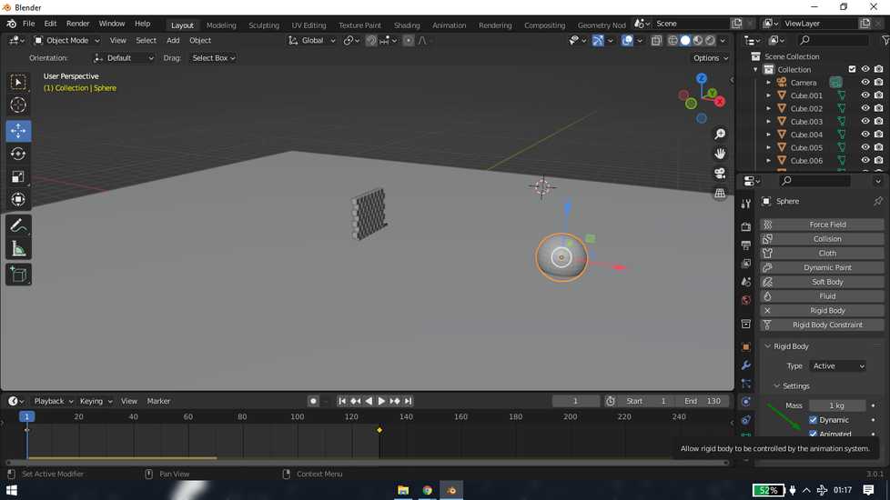
select the sphere and set the rigid body type as "active" and check the "animated" button
here is the result
<<<---CLOTH--->>>
add a sphere and a plane and set them at a distance
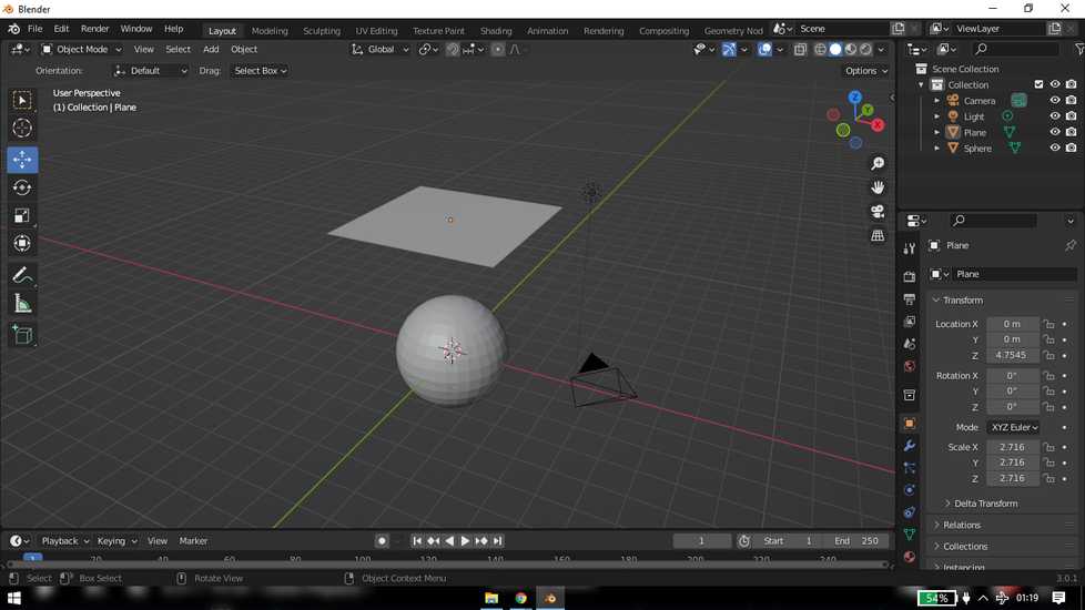
set the plane as cloth from Physics property
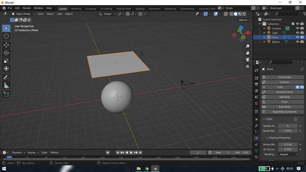
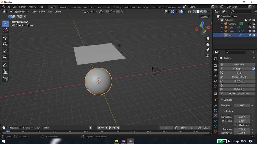
set the sphere as collision
If you directly hit play, the plane won't behave as a cloth. So inside edit mode,right-click on plane and increase number of cuts.
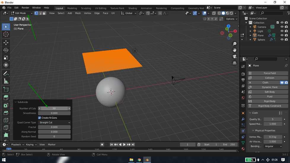
here is the result
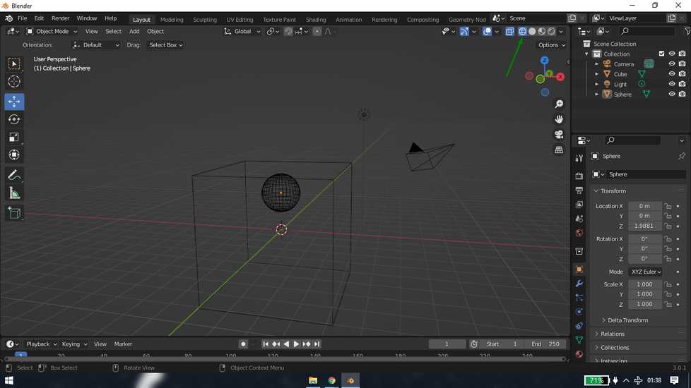
<<<---FLOW--->>>
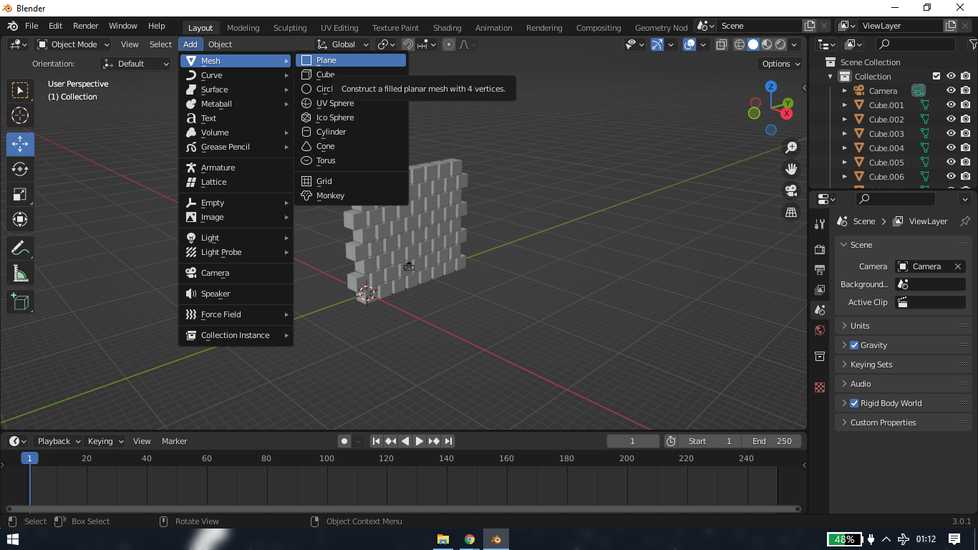
add a cube. add a sphere. size them and place the sphere inside the cube so that it doesn't touch the cube. You select 3D view: Wireframe
from top.
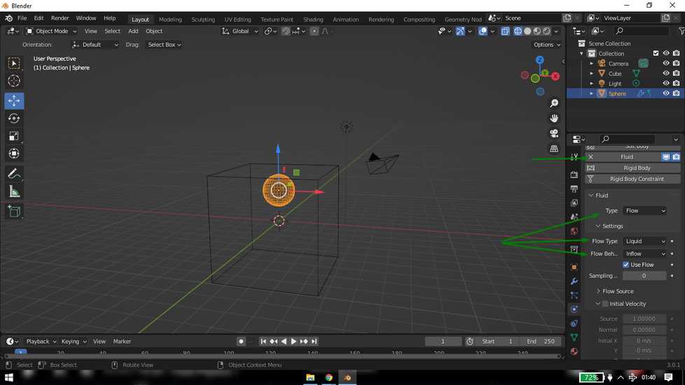
select sphere and under physics property select below settings
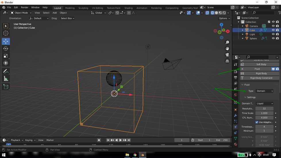
select cube and under physics property select below settings
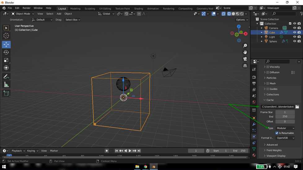
this will be the result after clicking "bake data"
enable mesh and click on"bake mesh"
here is the result
freecad
fusion
inkscape
solidworks
Learning Outcomes
This week i explored a bunch of editin and design softwares. There are few software that i like and use them on a regular basis and they are
lightshot, handbrake, xnconvert, fusion, solidworks and inkscape. I like soliworks because i ahve done a lot of practice, i have made 95/100 models from this website:
https://caddexpert.com/solidworks-catia-nx-autocad-3d-drawings-practice-books-100-pdf/ .
There is almost nothing I don't like about solidworks apart from the fact that it is very expensive software.
I like fusion because it is free(the education one) and designing a part is fun, however the assembling in fusion is something i don't like.
Software like lightshot, xnconvert, handbrake are bery easy to use and does it's job. On the other hand, there are softwares that i explored
just for the sake of the assignment and probably never going to use and those software are olive, freecad, blender and specially GIMP! The reason
why I don't like these softwares is because performing even the simplest of the task is a headache.
Drip Irritation by Fenil Chandarana is licensed under Attribution-NonCommercial-NoDerivatives 4.0 International![]()
![]()
![]()
![]()